AutoCAD Line Types & Hatch Patterns: A Comprehensive Guide
Introduction
AutoCAD is a powerful design and drafting software used by architects, engineers, and designers worldwide. Among its essential features are line types and hatch patterns, which help differentiate elements in drawings, improve readability, and convey material properties.
Understanding how to use and customize these features can significantly enhance your drafting efficiency and accuracy. This guide will cover everything you need to know about AutoCAD line types and hatch patterns, including their purpose, customization, troubleshooting, and best practices.
1. Understanding AutoCAD Line Types
1.1 What Are Line Types in AutoCAD?
Line types in AutoCAD are predefined or user-defined patterns that define how lines appear in a drawing. Instead of displaying as continuous lines, they can be dashed, dotted, or include text/symbols.
Common line types include:
- Continuous (_________)
- Dashed (
_ _ _ _) - Dotted (
· · · ·) - Dash-Dot (
_ · _ ·) - Centerline (
____ _ ____) - Phantom (
__ __ __)
1.2 Why Use Different Line Types?
Different line types help distinguish between various elements in technical drawings:
- Hidden lines (dashed) indicate obscured edges.
- Centerlines mark symmetry or center points.
- Construction lines (phantom) guide design without being part of the final output.
- Border lines (continuous) define drawing boundaries.
1.3 How to Load and Apply Line Types
AutoCAD comes with default line types, but you can also load additional ones or create custom patterns.
Steps to Load a Line Type:
- Open the Layer Properties Manager (
LAcommand). - Click on the Line Type column for a layer.
- In the Select Line Type dialog, click Load.
- Choose from the available line types or browse a
.linfile. - Click OK to apply.
Steps to Assign a Line Type to an Object:
- Method 1: Assign via Layer Properties (recommended for consistency).
- Method 2: Use the Properties Panel (
CTRL+1) to override line types for individual objects.
1.4 Creating Custom Line Types
AutoCAD allows users to define custom line types using a .lin file.
Basic Syntax for a Simple Line Type:
*LINETYPE_NAME,Description
A, PATTERN_DESCRIPTION
- Example (Dash-Dot):
Copy
*DASHDOT,Dash Dot _ . _ . _ . _
A,.5,-.25,0,-.25
A= Alignment (start and end with a dash)..5= 0.5 unit dash.-.25= 0.25 unit gap.0= A dot (zero-length dash).-.25= Another gap.
Adding Text or Shapes in Line Types:
You can embed text or symbols:
*FENCELINE,Fence line ----X----X----
A,.5,-.1,["X",STANDARD,S=.1,R=0.0,X=-0.1,Y=-.05],-.2
"X"= Text to display.STANDARD= Text style.S=.1= Scale.R=0.0= Rotation.X/Y= Offset adjustments.
1.5 Troubleshooting Line Type Issues
- Line Type Scale Too Small/Large?
AdjustLTSCALE(global scale) orCELTSCALE(object-specific scale). - Lines Appear Continuous?
CheckPSLTSCALE(paper space scaling) or zoom level (useREGEN). - Custom Line Type Not Loading?
Ensure the.linfile is in AutoCAD’s support path.
2. Mastering AutoCAD Hatch Patterns
2.1 What Are Hatch Patterns?
Hatch patterns are repeating designs used to fill enclosed areas, representing materials like concrete, brick, or insulation. They help differentiate sections, indicate materials, and add clarity to drawings.
Read More: AutoCAD Line Types & Hatch Patterns
2.2 Types of Hatch Patterns
- Predefined: Default patterns in AutoCAD (ANSI, ISO, etc.).
- User-Defined: Simple custom patterns (parallel lines, crosshatch).
- Custom: Complex patterns imported via
.patfiles.
2.3 Applying Hatch Patterns
Steps to Apply Hatch:
- Type
HATCHorHin the command line. - Select a boundary or pick points inside a closed area.
- Choose a pattern from the Hatch Creation tab.
- Adjust scale, angle, and transparency.
- Press Enter to apply.
2.4 Custom Hatch Patterns
AutoCAD allows custom hatch patterns defined in .pat files.
Basic Hatch Pattern Syntax:
*PATTERN_NAME,Description
Angle, X-Origin, Y-Origin, Delta-X, Delta-Y, Dash1, Dash2, ...
- Example (Brick Hatch):
Copy
*BRICK, Brick pattern
0, 0, 0, 0, 0.25
90, 0, 0, 0.5, 0.5, 0.5, -0.5
- First line: Horizontal bricks.
- Second line: Vertical staggered bricks.
2.5 Troubleshooting Hatch Issues
- Hatch Not Visible?
CheckFILLMODE(set to1) or adjust scale (HPSCALE). - Gaps in Boundary?
UseHATCHGAPtolerance or redraw the boundary. - Performance Lag?
Simplify complex hatches or useSOLIDfill where possible.
3. Best Practices for Using Line Types & Hatch Patterns
- Use Layers Wisely – Assign line types and hatches to layers for better control.
- Consistent Scaling – Ensure
LTSCALEandHPSCALEmatch drawing units. - Avoid Overcomplicating – Too many custom patterns can slow down AutoCAD.
- Test Before Finalizing – Preview hatches and line types in both model and paper space.
- Document Custom Patterns – Keep a library of
.linand.patfiles for reuse.
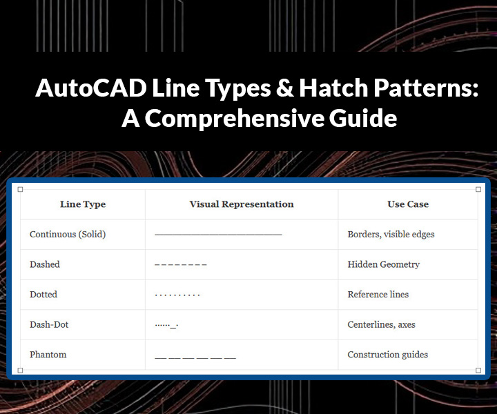
IMG-E1: Common AutoCAD Line Types (Visual Chart)
Description:
A side-by-side comparison of standard AutoCAD line types with labels.
Suggested Layout:
| Line Type | Visual Representation | Use Case |
|---|---|---|
| Continuous (Solid) | ━━━━━━━━━━━━━━ | Borders, visible edges |
| Dashed | ‒ ‒ ‒ ‒ ‒ ‒ ‒ ‒ | Hidden Geometry |
| Dotted | · · · · · · · · · · | Reference lines |
| Dash-Dot | ······_· | Centerlines, axes |
| Phantom | __ __ __ __ __ __ | Construction guides |
Design Tip:
- Use black lines on a white background for clarity.
- Add a legend explaining scale (e.g., “LTSCALE = 1.0”).
IMG-E2: Hatch Pattern Examples (Grid-Style Graphic)
Description:
A grid showing different hatch patterns with labels.
Suggested Layout:
- ANSI31 (Parallel lines at 45°) → Represents steel.
- AR-BRICK (Brick pattern) → Used for masonry walls.
- AR-CONC (Concrete texture) → For concrete sections.
- SOLID (100% fill) → For solid materials.
Visual Style:
- Display each hatch in a small square sample (e.g., 1″x1″).
- Include the pattern name and common applications below each sample.
IMG-E3: Custom Line Type Creation Flowchart
Description:
A step-by-step diagram showing how to create a custom line type.
Steps to Illustrate:
- Open Notepad → Create a
.linfile. - Define the pattern (e.g.,
*GAS_LINE, Gas Line ----G----G----). - Save the file in AutoCAD’s support path.
- Load in AutoCAD via
LINETYPEcommand. - Apply to layers/objects.
Design Tip:
- Use arrows to connect steps.
- Add a screenshot mockup of the
.linfile code snippet.
IMG-E4: Troubleshooting Hatch Issues (Infographic)
Description:
A visual guide to fixing common hatch problems.
Content Ideas:
- “Hatch Not Visible?” → Check
FILLMODEorHPSCALE. - “Gaps in Boundary?” → Use
HATCHGAPor redraw. - “Slow Performance?” → Simplify complex patterns.
Visual Style:
- Use red warning icons (⚠️) for issues and green checkmarks (✓) for solutions.
- Keep text minimal; focus on visuals.
IMG-E5: Line Type Scale Comparison (Before/After)
Description:
Two identical drawings showing the effect of LTSCALE adjustments.
Example:
- Before: Dashed lines too dense (
LTSCALE = 0.5). - After: Dashed lines correctly spaced (
LTSCALE = 1.0).
Design Tip:
- Label each image clearly (e.g., “LTSCALE Too Small” vs. “Optimal LTSCALE”).
How to Create These Images
- For Vector Graphics: Use AutoCAD (for technical accuracy) or Illustrator/Inkscape.
- For Quick Graphics: Canva or PowerPoint (using shapes and text boxes).
- For Screenshots: Capture real AutoCAD examples and annotate them.
Conclusion
Mastering AutoCAD line types and hatch patterns is crucial for professional drafting. Whether you’re using default styles or creating custom designs, these tools enhance drawing clarity and efficiency. By following best practices and troubleshooting common issues, you can optimize your workflow and produce high-quality technical drawings.
For advanced users, exploring AutoLISP scripts or third-party hatch libraries can further expand customization options. Keep experimenting and refining your techniques to stay ahead in CAD design!
