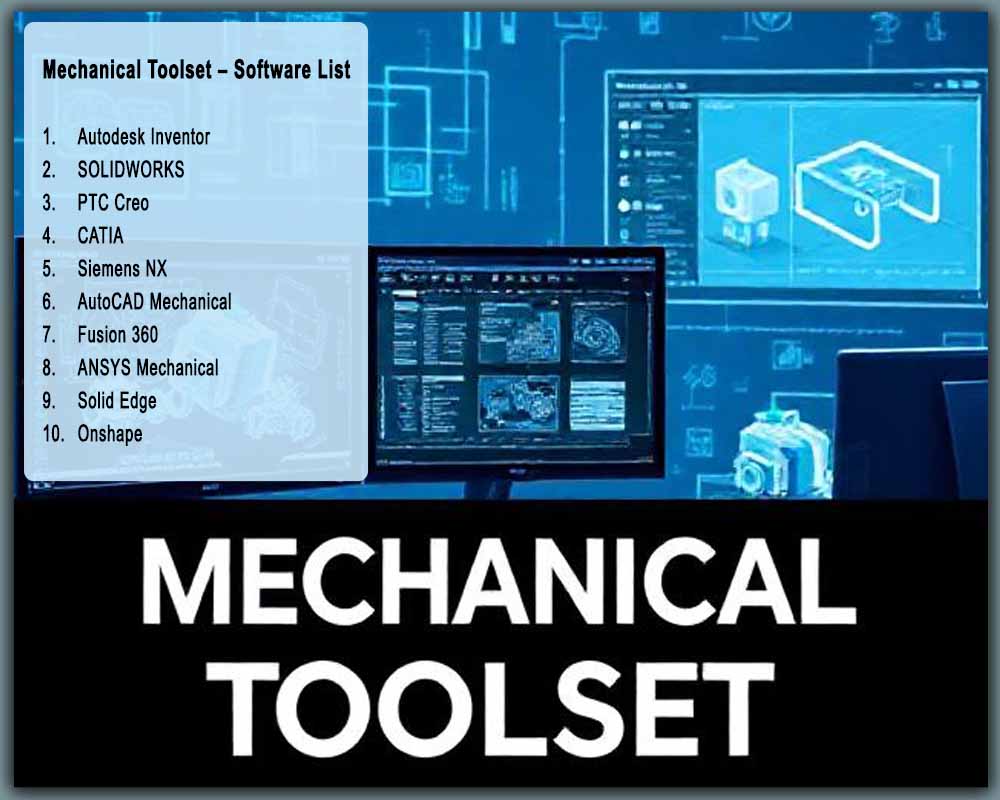
Mechanical Toolset: Top 10 Essential Software for Modern Mechanical Engineers and Designers
Introduction: The Digital Backbone of Modern Mechanical Engineering
Imagine designing a complex assembly like a car engine or a medical device using only pen, paper, and a slide rule. It’s an almost unthinkable notion today. The field of mechanical engineering has been utterly transformed by the power of digital tools, moving from drafting boards to sophisticated software suites that create, simulate, and validate designs in a virtual environment. This collection of software is what we call the Modern Mechanical Toolset—a digital arsenal that is as fundamental to an engineer as a wrench or a caliper.
But why is specialized software so critical? It boils down to complexity, efficiency, and innovation. Modern products are not just mechanical; they are often mechatronic systems integrating electronics and software. Specialized tools allow engineers to manage this complexity, test ideas under extreme conditions without physical cost, and iterate designs at an unprecedented speed. This digital thread connects every stage of a product’s life, from a spark of an idea to its final manufacture and even its service life.
To understand this toolset, we must first decode the core acronyms:
-
CAD (Computer-Aided Design): The foundation. This is for creating 2D drawings and 3D models of parts and assemblies. It’s the digital sketchpad where geometry is born.
-
CAE (Computer-Aided Engineering): The virtual testing lab. Using CAE tools like Finite Element Analysis (FEA) and Computational Fluid Dynamics (CFD), engineers simulate real-world forces, heat, and fluid flow on their CAD models to predict performance and find failures before a single prototype is built.
-
CAM (Computer-Aided Manufacturing): The bridge to the physical world. CAM software uses the CAD model to generate toolpaths and G-code that instruct CNC machines (like mills, lathes, and 3D printers) on how to manufacture the part.
-
PLM (Product Lifecycle Management): The central nervous system. PLM is a strategic system that manages all the data and processes related to a product from its conception, through design and manufacture, to service and disposal.
In today’s competitive landscape, proficiency in a single software is no longer enough. A versatile mechanical engineer or designer must have multi-software knowledge. You might use SOLIDWORKS for detailed machine design, ANSYS for advanced simulation, and Siemens NX within a large enterprise for its integrated PLM capabilities. Understanding the strengths and specializations of each tool in the toolbox makes you a more adaptable, valuable, and innovative professional.
This comprehensive guide will walk you through the top 10 essential software that form the core of the modern mechanical toolset.
The Top 10 Mechanical Engineering Software Deep Dive
01. Autodesk Inventor
What Is This Software?
Autodesk Inventor is a professional-grade 3D CAD software focused on mechanical design, documentation, and product simulation. It operates on a parametric, history-based modeling approach, meaning your design intent is built into the model through a timeline of features, making edits and updates predictable and robust. It’s particularly renowned for its powerful tools for creating complex assemblies and its seamless integration with other Autodesk products.
Who Can Use It?
-
Mechanical Engineers and Designers working on machinery, product design, and industrial equipment.
-
Manufacturing Teams for creating detailed manufacturing drawings and documentation.
-
Students learning parametric 3D design principles.
-
R&D Teams that require strong simulation and visualization capabilities.
Why Should You Use It?
Inventor shines in automating design tasks. Its iLogic feature allows you to create rule-driven designs, where changing a few parameters can automatically reconfigure an entire assembly. Its native integration with AutoCAD is a massive benefit for firms transitioning from 2D to 3D. The workflow typically involves creating 3D parts, assembling them into a full product, running motion and stress simulations, and then generating production-ready 2D drawings automatically.
Key Features
-
Parametric & Direct Modeling: Flexible modeling approaches for both structured design and fast conceptual work.
-
Powerful Assembly Modeling: Tools for managing large assemblies with thousands of components efficiently.
-
iLogic: Rule-based design automation to create configurable products and automate repetitive tasks.
-
Integrated FEA & Motion Simulation: Stress analysis and dynamic motion studies within the same environment.
-
Automated Drawing Creation: Generate standard-compliant 2D drawings with bill of materials (BOM) from 3D models.
-
Frame Generator: Quickly design and document structural frames from standard profiles.
-
Sheet Metal Design: Dedicated tools for creating flat patterns and 3D models of sheet metal components.
-
Native DWG Support: Seamlessly work with 2D AutoCAD drawings.
Where Can You Download or Learn It?
-
Available on the Autodesk official website.
-
Training available on Udemy, Coursera, LinkedIn Learning, and YouTube.
Tips & Tricks
-
Master iLogic early to automate families of parts and standardize your designs.
-
Use the “Shrinkwrap” tool to create simplified versions of complex assemblies for sharing or for use in higher-level assemblies.
-
Leverage the “Derive” component feature to create multiple part configurations from a single “master” part file.
-
Utilize the “Pattern & Mirror” features in assemblies to quickly populate components.
-
For large assemblies, use “Level of Detail” representations to suppress components that are not currently needed, improving performance.
Final Thoughts
Autodesk Inventor is a robust, all-in-one solution for mechanical design that balances power with a relatively gentle learning curve, making it a cornerstone for many small to mid-sized manufacturing and design firms.
02. SOLIDWORKS
What Is This Software?
SOLIDWORKS, developed by Dassault Systèmes, is one of the most popular and widely used 3D CAD software in the world. It set the standard for the Windows-native, parametric, feature-based approach to 3D solid modeling. Its intuitive interface and powerful core modeling tools have made it a go-to solution for millions of engineers.
Who Can Use It?
-
Product Designers and Mechanical Engineers across all industries.
-
Students and Educators (with heavily discounted licenses).
-
Manufacturing and Prototyping Shops.
-
Simulation Engineers using its integrated SOLIDWORKS Simulation suite.
Why Should You Use It?
SOLIDWORKS is celebrated for its user-friendliness and powerful core modeling capabilities. It enables a highly intuitive design process where you sketch, create features, and build assemblies with logical, easy-to-understand steps. Its massive user community means finding tutorials, help, and third-party components is exceptionally easy. The typical workflow is a streamlined version of the standard CAD process: Part -> Assembly -> Drawing -> Simulation.
Key Features
-
User-Friendly Interface: Command Manager and context-sensitive right-click menus make for an efficient workflow.
-
Powerful Part & Assembly Modeling: Robust extrude, revolve, loft, and sweep features with comprehensive mating tools for assemblies.
-
SOLIDWORKS Simulation: Integrated FEA for stress, displacement, frequency, and thermal analysis.
-
SOLIDWORKS Flow Simulation: Integrated CFD for fluid flow and heat transfer analysis.
-
Sheet Metal & Weldment Tools: Dedicated environments for sheet metal and structural member design.
-
PhotoView 360: Integrated, high-quality rendering for creating photorealistic images.
-
eDrawings: A lightweight collaboration tool for sharing and marking up designs with anyone.
-
Design Checker: Automatically ensures drawings and models adhere to company standards.
Where Can You Download or Learn It?
-
Downloadable from the Dassault Systèmes official SOLIDWORKS portal.
-
Training available on Udemy, Coursera, LinkedIn Learning, YouTube, and the official SOLIDWORKS website.
Tips & Tricks
-
Fully define your sketches! This prevents unexpected changes and is a fundamental best practice.
-
Use “Configurations” to manage different versions of a part or assembly (e.g., different sizes, materials, or simplified models for simulation) within a single file.
-
Learn the “Pack and Go” feature to easily collect all related files (parts, drawings, assemblies) when sharing a project.
-
Use “Design Tables” to drive configurations and parameters directly from Microsoft Excel.
-
For complex shapes, master the “Sweep” and “Loft” features with guide curves.
Final Thoughts
SOLIDWORKS remains the gold standard for accessible, powerful 3D mechanical CAD. Its blend of a shallow learning curve and deep functionality makes it an essential first professional CAD software for many engineers and a daily driver for countless others.
03. PTC Creo
What Is This Software?
PTC Creo is a scalable, suite of 3D CAD software built for the challenges of advanced, multi-disciplinary product development. It’s known for its powerful parametric modeling, robust surfacing capabilities, and deep integration with IoT and Augmented Reality (AR) through its parent company, PTC.
Who Can Use It?
-
Expert Mechanical Engineers in aerospace, automotive, and high-tech industries.
-
R&D Teams working on complex, innovative products.
-
Engineers requiring high-end surfacing for ergonomic and aesthetic design.
-
Large enterprises needing scalability and integration with Windchill PLM.
Why Should You Use It?
Creo excels at handling extremely complex product designs. Its “Unite Technology” allows it to open and work with native files from other CAD systems (like SOLIDWORKS or NX) without data conversion, a huge benefit in collaborative environments. It’s designed for high-performance, pushing the boundaries of what’s possible in parametric design, especially with its Freestyle surfacing tools for organic shapes.
Key Features
-
Parametric, Direct, and Freeform Modeling: A multi-pronged approach to suit any design style.
-
Creo Simulation Live: Real-time FEA feedback integrated directly into the modeling environment.
-
Advanced Surfacing (ISDX): Industry-leading interactive surface design extension for complex Class-A surfaces.
-
Top-Down Design: Powerful tools for designing within the context of an overall assembly layout.
-
Generative Design: Automatically explore multiple design alternatives based on weight, cost, and manufacturing constraints.
-
Additive Manufacturing Module: Advanced tools for designing and preparing parts for 3D printing.
-
Creo Illustrate: Creates interactive 3D technical illustrations for service and maintenance manuals.
Where Can You Download or Learn It?
-
Available on the PTC official website.
-
Training available on Udemy, PTC University, and LinkedIn Learning.
Tips & Tricks
-
Use the “Flexible Modeling” extension for direct editing of imported geometry.
-
Leverage “Top-Down Design” with skeleton models to control entire assemblies from a single master layout.
-
Master the “Style” (ISDX) feature for creating complex, curvature-continuous surfaces.
-
Utilize Creo Simulation Live during the design phase for instant feedback on structural integrity.
-
Explore the “Generative Design” capabilities to discover optimized, lightweight designs you might not have conceived manually.
Final Thoughts
PTC Creo is a high-end, powerful CAD solution for enterprises and experts tackling the most demanding design challenges, particularly where collaboration, complex surfacing, and integration with IoT are paramount.
04. CATIA
H4: What Is This Software?
CATIA (Computer-Aided Three-dimensional Interactive Application) is the high-end flagship CAD/CAM/CAE platform from Dassault Systèmes. It is a multi-platform suite used for product design, engineering, and systems modeling. CATIA is less of a single tool and more of a comprehensive product development environment.
Who Can Use It?
-
Systems Engineers and Architects in aerospace, automotive, and shipbuilding.
-
Mechanical Engineers designing complex surfaces and complex systems.
-
Class-A Surfacing Specialists.
-
Large corporations requiring robust PLM integration (via ENOVIA).
Why Should You Use It?
CATIA is the industry standard for complex, systems-level engineering. It is famously used by Boeing to design its entire aircraft digitally. Its strength lies in its ability to manage extremely large assemblies and its unparalleled surface modeling capabilities, enabling the design of everything from the airfoil of a wing to the ergonomic curve of a car body.
Key Features
-
Systems Engineering: Manages the complex relationships between mechanical, electronic, and software components.
-
Class-A Surfacing: The industry benchmark for creating aesthetically perfect, high-quality surfaces.
-
Comprehensive Assembly Design: Tools for managing massive assemblies with millions of parts.
-
Integrated Engineering Applications: Covers everything from 3D design to analysis, simulation, and manufacturing.
-
BIM (Building Information Modeling): Powerful tools for architectural and construction projects.
-
Seamless PLM Integration: The backbone of Dassault’s 3DEXPERIENCE platform.
Where Can You Download or Learn It?
-
Available through the Dassault Systèmes official website.
-
Training is typically provided by Dassault partners and specialized training centers.
Tips & Tricks
-
Focus on understanding the “Sketcher” and “Part Design” workbenches thoroughly as they are the foundation.
-
Learn the “Generative Shape Design” workbench for advanced surface creation.
-
Utilize the “Knowledgeware” features to embed engineering intelligence and rules into your models.
-
Master the use of the “Compass” for navigating and orienting yourself in large, complex models.
-
Structure your data meticulously from the beginning, as CATIA projects are inherently complex.
Final Thoughts
CATIA is the pinnacle of CAD/CAM/CAE software, aimed at the top tier of manufacturing. It is not for casual users but is an essential tool for engineers working on the world’s most complex products.
05. Siemens NX
What Is This Software?
Siemens NX, formerly Unigraphics, is a high-end, integrated CAD/CAM/CAE solution from Siemens Digital Industries Software. It is a direct competitor to CATIA and Creo, known for its “Synchronous Technology,” which combines the power of parametric history-based modeling with the flexibility of direct modeling.
Who Can Use It?
-
Mechanical Engineers in automotive, aerospace, and medical device industries.
-
Manufacturing Engineers for high-end CNC programming.
-
Simulation Analysts requiring integrated advanced CAE.
-
Companies deeply invested in the Siemens Teamcenter PLM ecosystem.
Why Should You Use It?
NX’s killer feature is Synchronous Technology. It allows you to edit any model—whether you created it or it was imported from another CAD system—quickly and without being constrained by the model’s history tree. This makes it incredibly powerful for working with supplier data and making rapid design changes late in the development process.
Key Features
-
Synchronous Technology: A game-changing hybrid modeling environment.
-
Integrated CAD/CAM/CAE: A seamless workflow from design to simulation to manufacturing.
-
Advanced Surfacing: Powerful tools for creating production-quality surfaces.
-
Reverse Engineering: Tools to convert 3D scan data into usable, editable CAD models.
-
Robust Data Management: Tight integration with Teamcenter PLM.
-
Generative Design: Like Creo and Fusion 360, it offers AI-driven design exploration.
Where Can You Download or Learn It?
-
Available on the Siemens official website.
-
Training available through Siemens partners and platforms like Udemy and Pluralsight.
Tips & Tricks
-
Leverage “Synchronous Technology” to quickly modify imported geometry from other CAD systems.
-
Use the “Wave Link” and “Skeleton Modeling” for robust top-down assembly design.
-
Explore the “Convergent Modeling” tools for working with facet data (from 3D scans).
-
Master the “Sketch” constraints in the history-based mode to build stable parametric models.
-
Utilize the “Drafting” environment to create highly detailed and standardized 2D documentation.
Final Thoughts
Siemens NX is a powerhouse for integrated product development, offering unparalleled flexibility in modeling and a seamless connection to PLM and advanced manufacturing, making it a top choice for large, innovative enterprises.
06. AutoCAD Mechanical
H4: What Is This Software?
AutoCAD Mechanical is a specialized version of the legendary AutoCAD software, turbocharged with tools and libraries specifically for mechanical engineering design and drafting. It is built on the 2D drafting paradigm but adds immense intelligence and automation.
Who Can Use It?
-
Drafters and Detailers creating production drawings.
-
Mechanical Engineers who primarily work in or need to maintain 2D standards.
-
Manufacturing shops that rely on detailed 2D documentation.
-
Professionals in industries where 2D is still the standard.
Why Should You Use It?
If your work revolves around creating detailed, standard-compliant 2D manufacturing drawings, AutoCAD Mechanical is the most efficient tool for the job. It automates tedious tasks like generating BOMs, adding dimensions, and drawing standard components, saving vast amounts of time compared to vanilla AutoCAD.
Key Features
-
700,000+ Standard Parts Library: Huge library of screws, nuts, bearings, and more, ready to insert.
-
Layer Management: Automated and standardized layer names for different drawing elements.
-
Power Dimensioning: Automated creation of dimensions and hole charts.
-
Mechanical Calculator: Tools for calculating shafts, springs, belts, and chains.
-
Standards Checker: Ensures your drawings comply with ISO, ANSI, or other standards.
-
Intelligent Manufacturing Drawing Creation: Automated view creation and BOM generation.
Where Can You Download or Learn It?
-
Available on the Autodesk official website.
-
Training available on Udemy, Coursera, LinkedIn Learning, and YouTube.
Tips & Tricks
-
Use the “AMSTANDARD” command to configure the software to your company’s or project’s drafting standard.
-
Master the “Content Library” palette to quickly drag and drop standard components into your drawings.
-
Utilize the “Power Dimension” commands for fast, accurate, and standard-compliant dimensioning.
-
Leverage the “Mechanical Structure” to organize your drawing files and manage BOM data intelligently.
-
Use the “Calculator” tools (e.g., shaft calculation) to inform your design decisions directly within the drafting environment.
Final Thoughts
While the world moves to 3D, 2D drafting remains the legal language of manufacturing. AutoCAD Mechanical is the ultimate tool for speaking this language with maximum efficiency and precision.
07. Fusion 360
What Is This Software?
Fusion 360 is Autodesk’s cloud-based, all-in-one CAD, CAM, CAE, and PCB platform. It breaks down the traditional barriers between different engineering disciplines by unifying the entire product development process in a single, collaborative environment that lives in the cloud.
Who Can Use It?
-
Product Designers, Hobbyists, and Startups.
-
Mechanical Engineers working in collaborative, distributed teams.
-
Makers and CNC Machinists.
-
Engineers needing integrated CAD + CAM + Simulation without high-cost data management.
Why Should You Use It?
Fusion 360’s greatest strength is its integration and accessibility. It combines parametric, direct, surface, and mesh modeling with simulation, rendering, and manufacturing in one affordable package. The cloud-based platform enables seamless collaboration, version control, and data sharing, making it ideal for small teams and freelance designers.
Key Features
-
Cloud-Collaboration: Multiple users can work on the same design simultaneously.
-
Integrated CAD/CAM/CAE/PCB: A truly unified workflow from concept to CNC code.
-
Generative Design: Powerful AI-driven design exploration that suggests optimized forms based on constraints.
-
Direct & Parametric Modeling: Flexible modeling for both quick concepts and detailed design.
-
Electronics & PCB Design: Integrated schematic and board layout capabilities.
-
Data Management: Built-in version control and project sharing.
Where Can You Download or Learn It?
-
Available on the Autodesk official website.
-
Training available on Udemy, Coursera, LinkedIn Learning, YouTube, and Autodesk Design Academy.
Tips & Tricks
-
Use “Components” instead of “Bodies” for assembly modeling to maintain a proper hierarchy.
-
Leverage the “Timeline” at the bottom to edit feature history, but use “Direct Editing” for quick fixes.
-
Explore “Generative Design” early in the process to explore radically different, optimized concepts.
-
Use the “In-Canvas Render” tool to get quick, presentable images without a full render.
-
Master the “Patch” workspace for complex surface modeling and repair.
Final Thoughts
Fusion 360 represents the future of collaborative, integrated design. It democratizes high-end engineering tools, making them accessible to a broader audience and breaking down silos between design, engineering, and manufacturing.
08. ANSYS Mechanical
What Is This Software?
ANSYS Mechanical is a dedicated, best-in-class Finite Element Analysis (FEA) software used to simulate and solve complex structural mechanics problems. It is not a CAD modeler; it is a CAE tool that imports CAD geometry to perform sophisticated simulations.
Who Can Use It?
-
Simulation Specialists and FEA Analysts.
-
Mechanical Engineers validating product performance and durability.
-
R&D Engineers in aerospace, automotive, and energy sectors.
-
Students learning advanced simulation techniques.
Why Should You Use It?
When the stakes are high and you need the most accurate and reliable simulation results, ANSYS is the industry standard. It can handle everything from linear static analysis (stress, strain) to complex nonlinear dynamics, explicit dynamics (impact), and fatigue. Its solvers are among the most robust and validated in the world.
Key Features
-
Advanced Contact Modeling: Accurately simulates how multiple parts interact and transfer loads.
-
Nonlinear Material Models: Simulates materials like plastics, rubbers, and composites that do not behave linearly.
-
Transient Structural & Explicit Dynamics: For analyzing events like crashes, drops, and explosions.
-
Fatigue Analysis: Predicts the life of a component under cyclic loading.
-
Comprehensive Meshing Tools: High-fidelity automatic and manual meshing capabilities.
-
Integration with ANSYS Workbench: A project-level tool that connects Mechanical with other ANSYS products (Fluids, Electromagnetics).
Where Can You Download or Learn It?
-
Available on the ANSYS official website.
-
Training available on the ANSYS Learning Hub, Coursera, edX, and YouTube.
Tips & Tricks
-
Always start with a simple analysis (e.g., linear static) to verify your setup before moving to complex simulations.
-
Pay extreme attention to meshing. Use mesh convergence studies to ensure your results are accurate.
-
Simplify your CAD geometry before importing by removing small fillets, holes, and other features not critical to the analysis.
-
Understand and correctly apply “Connections” (contacts, joints, springs) as they are critical to accurate results.
-
Leverage “Named Selections” to easily manage and select geometry for loads, constraints, and results.
Final Thoughts
ANSYS Mechanical is the definitive tool for high-fidelity engineering simulation. It is essential for any engineer or organization that requires the highest level of confidence in their virtual product validation.
09. Solid Edge
What Is This Software?
Solid Edge is a robust, mid-range CAD software from Siemens that offers a unique blend of history-based parametric modeling and synchronous technology, similar to its bigger sibling, NX. It is known for its ease of use and powerful tools for specific manufacturing processes.
Who Can Use It?
-
Mechanical Designers and Engineers in mainstream manufacturing.
-
Sheet Metal Designers and Fabricators.
-
Companies looking for a powerful CAD solution with a lower cost of entry than NX.
-
Users transitioning from SOLIDWORKS or Inventor.
Why Should You Use It?
Solid Edge provides a fantastic balance of power and usability. Its synchronous technology makes it easy to work with imported models and make rapid changes. It also includes some of the best-in-class tools for sheet metal design and routing for electrical harnesses and pipes, all within a well-integrated package.
Key Features
-
Synchronous Technology: Faster, more flexible editing of 3D models.
-
Advanced Sheet Metal Design: Flattening, unfolding, and documentation tools are top-tier.
-
XpresRoute: Easy-to-use tools for creating 3D routes for wires, tubes, and pipes.
-
Convergent Modeling: Edit and combine facet data (from 3D scans) with precise B-Rep geometry.
-
Integrated FEA & CFD Simulation: Solid Edge Simulation provides robust analysis capabilities.
-
Data Management: Built-in, Microsoft SharePoint-based data management.
Where Can You Download or Learn It?
-
Available on the Siemens official website.
-
Training available on Udemy, LinkedIn Learning, and the Siemens Learning website.
Tips & Tricks
-
Use the “Steal” feature from synchronous technology to copy faces from one part to another quickly.
-
Master the “Sheet Metal” environment for designing and unfolding complex sheet metal parts.
-
Utilize the “XpresRoute” tools to quickly create 3D harness and pipe layouts within an assembly.
-
Leverage the “Assembly Features” to cut or add material across multiple components at the assembly level.
-
Use the “Pattern” features driven by sketches for creating non-uniform patterns of components.
Final Thoughts
Solid Edge is a highly capable and often underrated contender in the CAD space, offering a unique synchronous approach that boosts productivity, especially for designers working with a mix of native and imported data.
10. Onshape
What Is This Software?
Onshape is a full-cloud, software-as-a-service (SaaS) professional 3D CAD platform. It requires no installation and runs entirely in a web browser or on a mobile app. It is built from the ground up for collaboration, featuring a unique database architecture that manages all design data.
Who Can Use It?
-
Distributed Design Teams and Remote Workers.
-
Product Designers and Engineers in fast-paced, collaborative environments.
-
Consultants and Freelancers who need to share progress with clients easily.
-
Students and Educators (with a free Education plan).
Why Should You Use It?
Onshape eliminates the headaches of traditional CAD file management. There are no files to save, copy, or lose. Everyone on the team always sees the latest version. Its branch-and-merge functionality allows designers to work on parallel ideas without interfering with each other, a game-changer for collaborative design. The instant deployment and platform independence (it runs on Windows, Mac, Linux, Chromebook) are huge advantages.
Key Features
-
Full-Cloud Native: No installation, automatic updates, and access from anywhere.
-
Real-Time Collaboration: Multiple users can edit the same document simultaneously.
-
Built-in Data Management: Version control, branching, and merging are inherent to the system.
-
Parametric & Direct Modeling: A modern, robust modeling kernel.
-
Standard Content Library: Access to millions of standard parts from within the browser.
-
Integrated Drawing & Rendering: Create 2D drawings and photorealistic renders in the same system.
Where Can You Download or Learn It?
-
Available on the Onshape official website (no download required).
-
Training available on the Onshape Learning Center, Udemy, and YouTube.
Tips & Tricks
-
Use “In-Context Modeling” to design parts within an assembly, creating robust relationships between components.
-
Master the use of “Part Studios” to organize multiple related parts in a single tab.
-
Leverage “Branching and Merging” to explore design alternatives without affecting the main design.
-
Use “Follow Mode” to watch a colleague design in real-time for easy collaboration and training.
-
Utilize “Custom Features” to save and reuse common design elements across your projects.
Final Thoughts
Onshape is not just another CAD tool; it’s a paradigm shift towards cloud-native, collaborative product development. It is essential for any team looking to break free from the constraints of file-based CAD and embrace a more agile, connected workflow.
Comparison Table: Mechanical Engineering Software at a Glance
| Software | Software Type | Best For | Skill Level | Supported Platforms |
|---|---|---|---|---|
| Autodesk Inventor | CAD, CAM, CAE | Machine Design, Product Design | Intermediate | Windows |
| SOLIDWORKS | CAD, CAM, CAE | General Mechanical Design, Product Design | Beginner to Intermediate | Windows |
| PTC Creo | CAD, CAM, CAE | Advanced Product Design, Complex Surfacing | Expert | Windows |
| CATIA | CAD, CAM, CAE, PLM | Systems Engineering, Class-A Surfacing, Aerospace | Expert | Windows |
| Siemens NX | CAD, CAM, CAE, PLM | Integrated Product Development, Advanced Manufacturing | Expert | Windows |
| AutoCAD Mechanical | 2D CAD | Mechanical Drafting & Detailing | Beginner to Intermediate | Windows, Mac |
| Fusion 360 | CAD, CAM, CAE, PCB | Collaborative Design, Startups, Hobbyists | Beginner to Intermediate | Windows, Mac, Cloud |
| ANSYS Mechanical | CAE (FEA) | Advanced Structural Simulation | Expert | Windows, Linux |
| Solid Edge | CAD, CAM, CAE | Mainstream Manufacturing, Sheet Metal | Intermediate | Windows |
| Onshape | CAD (Cloud) | Real-Time Collaboration, Distributed Teams | Beginner to Intermediate | Cloud (Any Platform) |
Frequently Asked Questions (FAQ)
Which mechanical design software is best for beginners?
For a complete beginner, SOLIDWORKS and Fusion 360 are excellent starting points. SOLIDWORKS has an intuitive interface and is the standard for many academic programs. Fusion 360 offers a gentler learning curve, a free personal-use license, and the benefit of learning an integrated, modern platform.
What is the difference between Inventor and SOLIDWORKS?
Both are direct competitors. SOLIDWORKS is often praised for its user-friendliness and massive third-party ecosystem. Inventor is deeply integrated with the Autodesk ecosystem (like AutoCAD and Vault) and offers powerful automation tools like iLogic. The choice often comes down to company preference and existing software investments.
Is Fusion 360 good for professional engineering?
Absolutely. While it’s popular with hobbyists, Fusion 360 is a powerful professional tool used by many engineering firms, especially startups and small-to-medium businesses. Its integrated CAD/CAM/CAE/PCB capabilities and cloud collaboration make it a highly efficient and cost-effective solution for professional product development.
What software is best for simulation?
ANSYS Mechanical is the industry leader for high-fidelity, advanced structural simulation. For integrated simulation that is “good enough” for most design validation tasks, the simulation tools within SOLIDWORKS, Inventor, Creo, and Fusion 360 are highly capable and more accessible.
Which mechanical software is used in the automotive industry?
The automotive industry relies heavily on high-end systems. CATIA is ubiquitous for body and chassis design (especially for Class-A surfaces), while Siemens NX is also widely used for detailed component and assembly design, as well as manufacturing. ANSYS is a standard for simulation.
Is there any free mechanical engineering software?
Yes, for students and hobbyists. Fusion 360 offers a free personal-use license with some limitations. Onshape has a free “Standard” plan for public documents. SOLIDWORKS offers a very affordable Student Edition. For pure 3D modeling, Blender (though not MCAD) is a powerful free and open-source option. Always check the licensing terms for commercial use.
Conclusion: Building Your Ultimate Mechanical Toolset
The modern mechanical engineer’s value is no longer defined solely by their theoretical knowledge but by their proficiency with the digital tools that bring ideas to life. The “mechanical toolset” is a dynamic and evolving collection of software, each with its own superpower.
There is no single “best” software; the best tool is the one that is right for the job, the team, and the stage of the product lifecycle. Students should start with SOLIDWORKS or Fusion 360 to build a strong foundation. Professionals in small to mid-sized firms will find immense value in the all-around capabilities of SOLIDWORKS, Inventor, or Solid Edge. Large enterprises tackling systems-level complexity will rely on the power of CATIA, Siemens NX, and PTC Creo. And for anyone working in a distributed, collaborative world, cloud-native platforms like Onshape and Fusion 360 are becoming indispensable.
By understanding the landscape and continuously developing your skills across this toolset, you equip yourself not just to design a better component, but to innovate, validate, and deliver the groundbreaking products of tomorrow. Invest in your digital toolbox—it is the engine of modern engineering innovation.
