


How to Link a CAD File in Revit (Step-by-Step Guide)
Linking a CAD file in Revit is one of the most useful workflows for architects, engineers, and architectural draftsmen who need to work with existing AutoCAD drawings. Whether you have a floor plan, site plan, elevation, or MEP layout, linking a DWG file allows you to use the original drawing as a reference while developing your Revit model.
Unlike importing, linking maintains a connection between the Revit project and the external CAD file. When the source drawing is updated and saved, you can reload the link to display those changes in Revit.
In this tutorial, you will learn how to link a CAD file in Revit, choose the correct import settings, control layer visibility, position the drawing accurately, update linked files, and solve common problems.
Quick Overview: Linking a CAD File in Revit
- Command: Insert → Link CAD
- Common file format: DWG
- Other supported formats: DXF, DGN, and certain additional CAD formats, depending on the Revit version
- Main purpose: Use an existing CAD drawing as a reference for Revit modeling or documentation
- Main advantage: Reload the linked file when the source drawing changes
- Best practice: Clean the CAD drawing before linking it and verify its units and positioning
1. Prepare Your CAD File Before Linking
Before opening Revit, spend a few minutes checking your AutoCAD drawing. A clean DWG file is easier to position, faster to display, and less likely to create visibility or performance problems.
Open the drawing in AutoCAD and check the following items.
Clean Unnecessary Objects
Remove unused geometry, duplicate lines, unnecessary hatches, temporary construction lines, and other information that is not required for your Revit workflow.
For example, if you are linking an architectural floor plan, you may not need the entire survey drawing, unrelated details, or every external reference included in the original file.
You can use the following AutoCAD commands where appropriate:
PURGE— remove unused definitions and other purgeable items.OVERKILL— identify and remove duplicate or overlapping geometry.AUDIT— check and attempt to correct drawing database errors.ZOOM→EXTENTS— inspect the overall drawing extents and identify objects far away from the intended plan.
Always review the drawing before deleting anything important.
Check the Drawing Units
Verify whether the CAD drawing was created in millimeters, meters, inches, or feet. Incorrect units can make a correctly drawn plan appear much too large or too small in Revit.
Also check the drawing origin and coordinates. For projects that require accurate coordination with other disciplines or survey data, preserve the agreed project coordinates instead of moving the drawing arbitrarily.
Save the Drawing
Save the cleaned drawing in a suitable DWG format compatible with your Revit version. Keep the original file as a backup if you are making significant changes.
Professional tip: Autodesk recommends cleaning unnecessary information from CAD files and avoiding unnecessary exploding of DWG geometry in Revit. These practices can help improve project performance.
2. Open Your Revit Project
Launch Revit and open the project in which you want to use the CAD drawing.
If you are starting a new project, select an appropriate architectural, structural, or MEP template.
Next, open the view where you want to link the CAD file.
For example:
- Open a floor plan to link an architectural layout.
- Open a reflected ceiling plan to reference a ceiling drawing.
- Open an elevation view to reference a CAD elevation.
- Open a suitable site or coordination view to work with a site plan.
The view you choose matters because the Current View Only setting determines whether the linked drawing is limited to the active view.
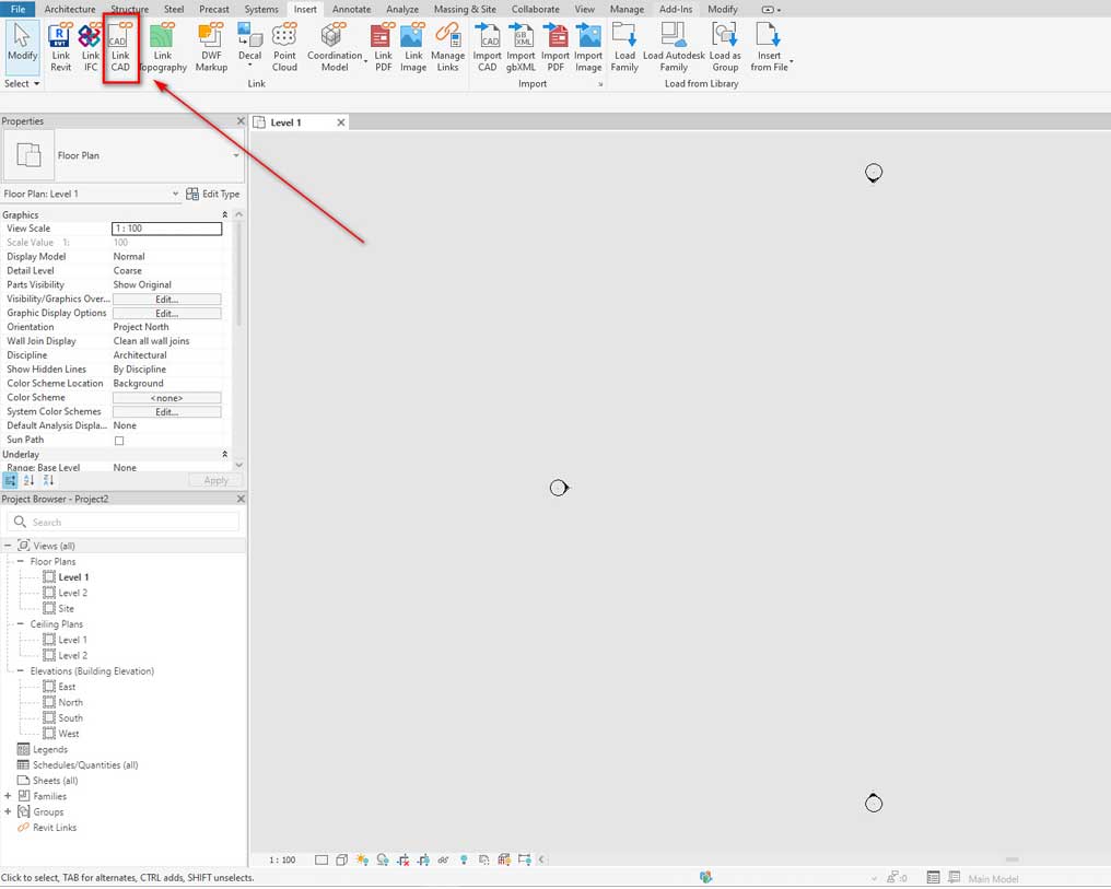
3. Use the Link CAD Command
Follow these steps to locate the CAD linking tool.
- Go to the Insert tab on the Revit ribbon.
- Locate the Link panel.
- Click Link CAD.
- In the file selection dialog, browse to the folder containing your CAD drawing.
- Select the required DWG file.
Make sure you choose Link CAD, not Import CAD, when you want to maintain a connection to the external file.
The Link CAD dialog contains several settings that control how the drawing appears in Revit. Review these options before clicking Open.
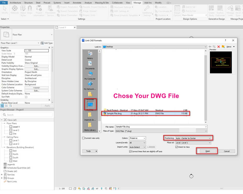
4. Choose the Correct CAD Linking Settings
The correct settings depend on your project requirements. The following options are particularly important when linking a DWG file into Revit.
A. Colors
The Colors option controls how the linked CAD drawing’s colors are displayed.
Common choices include:
- Preserve: Retains the CAD drawing’s color scheme as closely as Revit allows.
- Black and White: Displays the drawing in black and white.
- Invert: In supported Revit versions, reverses the CAD colors for improved visibility.
For an architectural floor plan, Black and White can be a useful starting point when you want the linked drawing to serve as a clean background for Revit walls, doors, and windows.
If the original CAD colors are important for distinguishing different systems or disciplines, consider Preserve instead.
B. Layers or Levels
This setting determines which layers from the CAD file are linked.
| Option | What it does | When to use it |
|---|---|---|
| All | Links all available layers, including layers that may be hidden in the source drawing | When you want maximum control over layer visibility later |
| Visible | Links layers that are visible in the saved CAD drawing | When you only need the currently visible drawing information |
| Specify | Allows you to select particular layers | When you need only selected information, such as walls and grids |
For most flexible architectural workflows, linking all layers can be helpful because you can control their visibility later through Revit’s Visibility/Graphics settings.
Important: If you link only selected layers, or use Visible, layers excluded at the time of linking may not become available simply by reloading the file. If you later need excluded layers, you may have to remove the link and link the CAD file again with different settings.
C. Import Units
Import Units determines how Revit interprets the measurements in the CAD file.
Depending on your Revit version and the selected file format, the available choices may include Auto-Detect and specific measurement units.
Common units include:
- Millimeters
- Centimeters
- Meters
- Inches
- Feet
For example, if your architectural drawing was created in millimeters, make sure Revit interprets the drawing using the correct units.
Auto-Detect can be convenient, but do not assume it is always correct. Verify the result by checking a known dimension after linking.
D. Positioning
Positioning determines where the CAD drawing is placed in the Revit project.
Depending on your project and Revit version, available options may include:
- Auto – Origin to Internal Origin: Places the source drawing’s origin at the Revit internal origin.
- Auto – Center to Center: Centers the CAD drawing relative to the Revit model.
- Manual positioning options: Allow you to place the linked drawing interactively or use other available placement methods.
For a simple floor plan that is not part of a shared-coordinate workflow, Origin to Internal Origin may be appropriate if the source drawing was prepared with a suitable origin.
For a coordinated project, the correct choice depends on how the CAD drawing and Revit model have been set up. Center to Center can be useful for an initial visual placement, but it does not establish accurate project coordinates.
Do not choose a positioning option without considering the project’s coordinate requirements.
E. Current View Only
Select Current View Only when you want the CAD drawing to appear only in the active view.
This can be useful when using a two-dimensional CAD drawing as an underlay for a particular floor plan or detail view.
If you leave this option unchecked, the linked drawing can be available in other relevant views, depending on the file and view configuration.
For most architectural floor-plan modeling tasks, choose the option that matches how you intend to use the drawing.
After reviewing these settings, click Open. If you selected Specify for layers, choose the required layers in the additional dialog.
Your CAD drawing is now linked to the Revit project.
For the complete explanation of available options, consult Autodesk’s official Link a CAD File documentation.
5. Check the Linked CAD Drawing in Revit
After linking the file, inspect the drawing before starting your Revit model.
Check the following:
- Visibility: Confirm that the drawing appears in the intended view.
- Scale: Compare a known dimension against the Revit measurement.
- Orientation: Verify that the drawing is aligned correctly.
- Position: Check that it is located where the project requires it.
- Layers: Confirm that the necessary drawing information is visible.
- Readability: Make sure the CAD lines do not obscure the Revit elements you need to create.
If the drawing does not appear immediately, check the view scale, crop region, visibility settings, and positioning before attempting to link it again.
Avoid moving a coordinated CAD link just to make it look centered on the screen. First determine whether its position is actually incorrect.
6. Control CAD Layer Visibility in Revit
One of the most useful benefits of linking a CAD file is that you can manage its appearance within Revit.
Suppose your architectural DWG contains the following layers:
- A-WALL — architectural walls
- A-DOOR — doors
- A-WIND — windows
- A-DIMS — dimensions
- A-FURN — furniture
- A-HATCH — hatch patterns
You may want to display the walls, doors, and windows while hiding furniture, dimensions, or hatch patterns during modeling.
To manage layer visibility:
- Open the view containing the linked CAD file.
- Type
VGorVVto open Visibility/Graphics Overrides. - Locate the Imported Categories tab.
- Expand the linked CAD file’s categories if necessary.
- Turn individual layers on or off as required.
- Click Apply or OK.
The exact controls may vary slightly between Revit versions and view configurations.
Remember that layer visibility is view-specific. A layer hidden in one view may still be visible in another.
7. Use the Linked CAD File to Create Your Revit Model
Once the drawing is positioned and its visibility is controlled, you can begin creating Revit elements using the CAD drawing as a reference.
For an architectural floor plan, a typical workflow is:
- Review the linked walls and room layout.
- Create or verify the required Revit levels.
- Use the Wall tool to model the walls.
- Place doors and windows in the appropriate locations.
- Create floors where required.
- Add stairs and other architectural elements.
- Check the model in plan, elevation, section, and 3D views.
The linked CAD file is a reference drawing; its lines do not automatically become native Revit walls, doors, floors, or windows.
You must create the appropriate Revit elements using the relevant modeling tools.
For example, a rectangle in AutoCAD may represent a wall or a column. Revit will not automatically know which element it represents simply because the geometry is present in the linked drawing.
Professional tip: Use the CAD file as a controlled reference and create native Revit elements wherever your project requires editable BIM geometry.
8. How to Update a Linked CAD File in Revit
One of the main advantages of linking rather than importing a CAD file is that you can update the reference when the source drawing changes.
Imagine that an architect sends you an updated floor plan with a relocated door and a revised wall layout. Instead of deleting the existing CAD drawing and linking it again, you can usually reload the linked file.
Follow these steps:
- Open the Revit project.
- Go to the Manage tab.
- Click Manage Links.
- Open the CAD Formats tab.
- Select the linked CAD file.
- Click Reload if the source file has changed and remains at the expected location.
- If the file has moved or been renamed, use the appropriate relinking or path-management option available in your Revit version.
After reloading, review the drawing to make sure the latest changes are visible.
If the source file changes while the Revit project is already open, you may need to reload it to retrieve the latest saved version.
Important: Reloading the CAD file updates the linked reference, but it does not automatically remodel your Revit walls, doors, windows, or other native elements to match the revised drawing. Review those elements and coordinate any required changes.
For more details, see Autodesk’s documentation about linking CAD files.
9. How to Fix Common CAD Linking Problems in Revit
Even when you follow the correct procedure, you may encounter problems. The following checks can help you identify the cause.
Problem 1: The CAD File Is Too Large or Too Small
Possible cause: The drawing units were interpreted incorrectly, or the source drawing was created at an unexpected scale.
Solution:
- Check the original AutoCAD drawing units.
- Review the Import Units setting.
- Confirm the expected measurement units in Revit.
- Measure a known distance in the linked drawing.
- Relink with the appropriate settings if necessary.
Do not scale a coordinated drawing arbitrarily to make it look correct. Confirm the intended units and coordinates first.
Problem 2: The CAD Drawing Is Not Visible
Possible causes: The link is outside the current view, the required layers were excluded, the drawing is hidden, or the view settings are incorrect.
Solution:
- Check whether the linked file appears in Manage Links.
- Open Visibility/Graphics and review Imported Categories.
- Confirm that the correct layers were linked.
- Check the crop region and view range where relevant.
- Inspect the source drawing in AutoCAD for objects located far from the intended geometry.
If the link was created using only selected layers, relink it with the necessary layers included when required.
Problem 3: The CAD File Appears in the Wrong Location
Possible cause: The drawing and Revit model use different origins or coordinate systems.
Solution:
- Check the source drawing’s coordinates in AutoCAD.
- Review the positioning option used during linking.
- Confirm the project’s agreed coordinate setup.
- For coordinated projects, follow the established shared-coordinate workflow.
Center to Center can help with an initial placement, but it should not replace proper coordinate coordination.
Problem 4: The CAD Drawing Looks Too Dark or Too Colorful
Possible cause: The linked drawing’s colors or linework make it difficult to distinguish from native Revit elements.
Solution:
- Review the Colors setting used when linking.
- Open Visibility/Graphics Overrides.
- Adjust the linked file’s layer visibility or graphic overrides where available.
- Hide unnecessary dimensions, hatches, or reference layers.
The best appearance depends on whether the CAD drawing is being used for modeling, coordination, or documentation.
Problem 5: Changes in AutoCAD Do Not Appear in Revit
Possible cause: The linked file has not been reloaded, the source changes were not saved, or Revit is referencing a different file path.
Solution:
- Save the updated DWG in AutoCAD.
- Return to Revit.
- Open Manage Links.
- Select the linked CAD file.
- Reload the file.
- Verify the path and confirm that the expected version is being used.
If the link points to a different copy of the DWG, correct the file path before continuing.
Problem 6: Revit Becomes Slow After Linking a DWG
Possible cause: The drawing contains excessive geometry, large hatch patterns, unnecessary external references, or other data that Revit does not need.
Solution:
- Clean the drawing in AutoCAD.
- Remove unnecessary objects and layers.
- Reduce unnecessary hatch patterns.
- Link only the required drawing information where appropriate.
- Avoid exploding the CAD file in Revit unless there is a specific technical reason.
These steps can improve performance, particularly when working with large architectural or engineering drawings.
10. Link CAD or Import CAD: Which Is Better?
Both options have their uses, but they serve different purposes.
| Feature | Link CAD | Import CAD |
|---|---|---|
| Maintains a connection to the source file | Yes | No |
| Can retrieve saved source changes by reloading | Yes | No |
| Useful as a reference for ongoing modeling | Yes | Sometimes |
| Automatically converts CAD geometry into native Revit elements | No | No |
| Suitable when the source drawing is expected to change | Usually preferred | Less suitable |
Recommendation: For architectural projects where the AutoCAD drawing may be revised during the design process, Link CAD is generally the better starting point. Import CAD can be appropriate when you need a static copy of the drawing inside the Revit project.
Neither method automatically converts ordinary CAD lines into intelligent Revit building elements.
11. Best Practices for Linking CAD Files in Revit
For a more reliable workflow, follow these recommendations:
- Clean before linking: Remove unnecessary geometry from the DWG file.
- Verify units: Check a known dimension after linking.
- Choose positioning carefully: Consider the project’s coordinate system before selecting a placement option.
- Control layers: Display only the information you need for the current task.
- Use sensible file paths: Keep linked files in an organized project folder or another location accessible to the team.
- Reload updated files: Make sure you are working with the latest saved reference drawing.
- Avoid unnecessary exploding: Keep CAD geometry linked unless there is a clear reason to do otherwise.
- Check the model after updates: Revised CAD geometry does not automatically update your native Revit elements.
- Coordinate with other disciplines: Follow the project’s procedures for shared coordinates, file naming, and drawing revisions.
Following these practices helps keep your Revit project organized, easier to maintain, and more reliable throughout the design process.
Frequently Asked Questions (FAQ)
Can I link a DWG file into Revit?
Yes. Open the Revit project, go to Insert → Link CAD, select your DWG file, review the settings, and click Open. Verify the drawing’s scale, position, and visibility after linking.
What is the difference between Link CAD and Import CAD in Revit?
Link CAD maintains a connection to the external drawing, allowing you to reload the latest saved version. Import CAD places a copy of the drawing in the project without maintaining the same ongoing link to the source file.
Why is my CAD file not showing in Revit?
Check the link status, layer selection, Imported Categories visibility, view crop, and drawing coordinates. Also verify that the source DWG contains visible geometry in the expected location.
How do I update a linked CAD file in Revit?
Save the revised DWG in AutoCAD, open Manage Links in Revit, select the linked file under CAD Formats, and click Reload. If the source file has moved, correct the path as necessary.
Can I hide individual CAD layers in Revit?
Yes. Open Visibility/Graphics Overrides, select Imported Categories, and control the visibility of available layers. The exact options depend on the link settings and Revit version.
Why does my linked CAD file have the wrong scale?
The most common issue is a mismatch between the drawing’s actual units and the units selected or detected during linking. Check a known dimension in the original drawing and verify the linked result before modeling.
Can I use a linked CAD floor plan to create Revit walls?
Yes. You can use the linked floor plan as a reference while creating native Revit walls, doors, windows, floors, and other elements. The CAD geometry itself does not automatically become those Revit elements.
Can I link a CAD file into a specific Revit view only?
Yes. Select Current View Only when linking the file if you want it restricted to the active view. This is useful for two-dimensional reference drawings.
Does linking a CAD file increase the Revit project file size?
A linked CAD file is managed differently from an imported copy, but it can still affect performance and project management. Large or complex linked drawings may slow down views. Cleaning the DWG and removing unnecessary information can help.
Which CAD file format should I use with Revit?
DWG is a common choice for AutoCAD drawings. Revit also supports other CAD formats, depending on the version and workflow. Always confirm that your chosen format is supported by your installed Revit release.
Conclusion
Linking a CAD file in Revit is a straightforward process, but choosing the correct units, layers, positioning, and visibility settings is essential for a reliable result.
Start by cleaning the source DWG in AutoCAD, use the Link CAD command in Revit, verify the drawing’s placement and scale, and manage layer visibility according to your modeling needs. When the source drawing changes, reload the link and review the affected Revit elements.
With a clean reference drawing and a consistent workflow, you can use existing AutoCAD plans more effectively while developing accurate, organized Revit models.
Explore more CAD and Revit resources on PINCAD. Find useful architectural drawings, CAD blocks, and design resources to support your next drafting or modeling project.
Browse PINCAD’s related CAD and Revit downloads to find reference files that fit your workflow.
Disclaimer: Revit interface options may vary by software version. Always verify drawing units, coordinates, and project requirements before using linked CAD geometry for professional documentation.
Related resources
